基于单区域OSPF协议互联的公司网络搭建
1.项目背景
Jan16公司有北京总部、广州分部和上海分部3个办公地点,各分部与总部之间使用路由器互联。公司要求通过配置单区域OSPF动态路由,实现公司之间能够互相访问。项目拓扑如图1所示,具体要求如下:
- 路由器R1、R2和R3通过VPN互联;
- R1、R2和R3之间网络通过单区域OSPF动态路由实现互联;
- 拓扑测试计算机和路由器的IP与接口信息如拓扑所示。
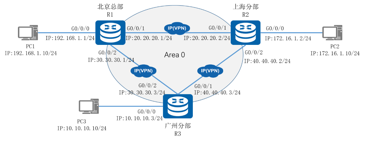
图1 网络拓扑图
2.项目规划设计
北京总部使用192.168.1.0网段,上海分部使用172.16.1.0网段,广州分部使用10.10.10.0网段,R1与R2之间为20.20.20.0网段,R1与R3之间为30.30.30.0网段,R2与R3之间为40.40.40.0网段,所有网段均使用24位子网掩码。路由器需配置单区域OSPF动态路由,使所有计算机均能互访。
配置步骤如下:
- 配置路由器接口
- 部署单区域OSPF网络
- 配置各计算机的IP地址与网关
业务规划如下表:
表1 IP地址规划表
设备 |
接口 |
IP地址 |
R1 |
G0/0/0 |
192.168.1.2/24 |
R1 |
G0/0/1 |
20.20.20.1/24 |
R1 |
G0/0/2 |
30.30.30.1/24 |
R2 |
G0/0/0 |
172.16.1.2/24 |
R2 |
G0/0/1 |
20.20.20.2/24 |
R2 |
G0/0/2 |
40.40.40.1/24 |
R3 |
G0/0/0 |
10.10.10.2/24 |
R3 |
G0/0/1 |
40.40.40.2/24 |
R3 |
G0/0/2 |
30.30.30.2/24 |
表2 接口规划表
本端设备 |
接口 |
端口IP地址 |
对端设备 |
R1 |
G0/0/0 |
192.168.1.2/24 |
PC1 |
R1 |
G0/0/1 |
20.20.20.1/24 |
R2 |
R1 |
G0/0/2 |
30.30.30.1/24 |
R3 |
R2 |
G0/0/0 |
172.16.1.2/24 |
PC2 |
R2 |
G0/0/1 |
20.20.20.2/24 |
R1 |
R2 |
G0/0/2 |
40.40.40.2/24 |
R3 |
R3 |
G0/0/0 |
10.10.10.2/24 |
PC3 |
R3 |
G0/0/1 |
40.40.40.1/24 |
R2 |
R3 |
G0/0/2 |
30.30.30.2/24 |
R1 |
3.项目实施
(1)配置略
(3)配置各计算机的IP地址
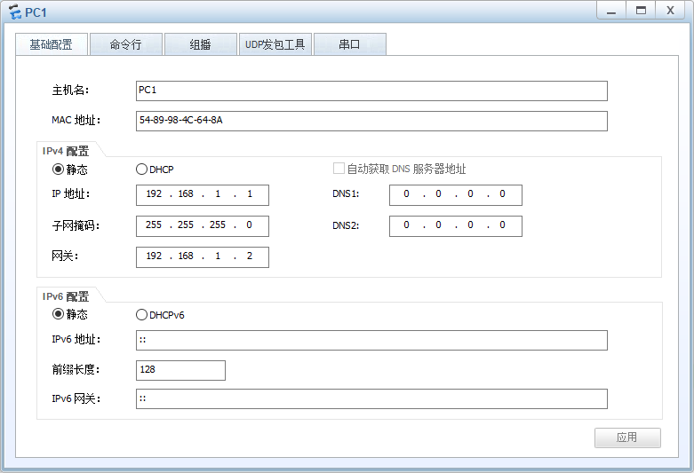
PC1 IP配置图
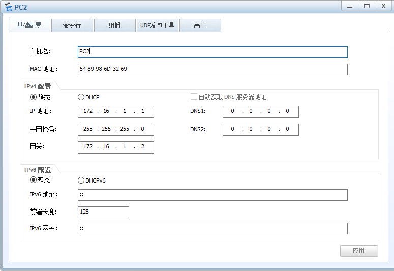
PC2 IP配置图
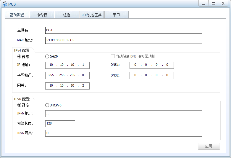
PC3 IP配置图
4.项目验证
(1)验证OSPF接口通告
- R1的配置
|
[R1]display ospf interface OSPF Process 1 with Router ID 192.168.1.2 Interfaces Area: 0.0.0.0 (MPLS TE not enabled) IP Address Type State Cost Pri DR BDR 192.168.1.2 Broadcast DR 1 1 192.168.1.2 0.0.0.0 20.20.20.1 Broadcast DR 1 1 20.20.20.1 20.20.20.2 30.30.30.1 Broadcast DR 1 1 30.30.30.1 30.30.30 |
- R2的配置
|
[R2]display ospf interface OSPF Process 1 with Router ID 172.16.1.2 Interfaces Area: 0.0.0.0 (MPLS TE not enabled) IP Address Type State Cost Pri DR BDR 172.16.1.2 Broadcast DR 1 1 172.16.1.2 0.0.0.0 20.20.20.2 Broadcast BDR 1 1 20.20.20.1 20.20.20.2 40.40.40.1 Broadcast DR 1 1 40.40.40.1 40.40.40.2 |
- R3的配置
|
[R3]display ospf interface OSPF Process 1 with Router ID 10.10.10.2 Interfaces Area: 0.0.0.0 (MPLS TE not enabled) IP Address Type State Cost Pri DR BDR 10.10.10.2 Broadcast DR 1 1 10.10.10.2 0.0.0.0 40.40.40.2 Broadcast BDR 1 1 40.40.40.1 40.40.40.2 30.30.30.2 Broadcast BDR 1 1 30.30.30.1 30.30.30.2 |
“Type”为以太网默认的广播网类型;“State”为该接口当前的状态,显示为DR状态。
(2)查看OSPF邻居状态
- SW1的配置
|
[R1]display ospf peer OSPF Process 1 with Router ID 192.168.1.2 Neighbors Area 0.0.0.0 interface 20.20.20.1(GigabitEthernet0/0/1)'s neighbors Router ID: 172.16.1.2 Address: 20.20.20.2 State: Full Mode:Nbr is Slave Priority: 1 DR: 20.20.20.1 BDR: 20.20.20.2 MTU: 0 Dead timer due in 37 sec Retrans timer interval: 5 Neighbor is up for 00:44:40 Authentication Sequence: [ 0 ] Neighbors Area 0.0.0.0 interface 30.30.30.1(GigabitEthernet0/0/2)'s neighbors Router ID: 10.10.10.2 Address: 30.30.30.2 State: Full Mode:Nbr is Slave Priority: 1 DR: 30.30.30.1 BDR: 30.30.30.2 MTU: 0 Dead timer due in 37 sec Retrans timer interval: 5 Neighbor is up for 00:42:48 Authentication Sequence: [ 0 ] |
通过这条命令,Router-ID可以查看邻居的路由器标识;通过Address可以查看邻居的OSPF接口IP地址;通过State可以查看目前与该路由器的OSPF的邻居状态;通过Priority可以查看当前该邻居OSPF接口的DR优先级。
(3)查看OSPF路由表
- R1的配置
|
[R1]display ip routing-table protocol ospf Route Flags: R - relay, D - download to fib ------------------------------------------------------------------------------ Public routing table : OSPF Destinations : 3 Routes : 4 OSPF routing table status : <Active> Destinations : 3 Routes : 4 Destination/Mask Proto Pre Cost Flags NextHop Interface 10.10.10.0/24 OSPF 10 2 D 30.30.30.2 GigabitEthernet0/0/2 40.40.40.0/24 OSPF 10 2 D 20.20.20.2 GigabitEthernet0/0/1 OSPF 10 2 D 30.30.30.2 GigabitEthernet0/0/2 172.16.1.0/24 OSPF 10 2 D 20.20.20.2 GigabitEthernet0/0/1 OSPF routing table status : <Inactive> Destinations : 0 Routes : 0 |
通过此路由表可以观察到,“Destination/Mask”标识了目的网段的前缀及掩码,“Proto”标识了此路由信息是通过OSPF协议获取的,“Pre”标识了路由优先级,“Cost”标识了开销值,“NextHop”标识了下一跳地址,“Interface”标识了此前缀的出接口。
(4)测试各部门计算机的互通性
通过Ping命令,测试各部门内部通信的情况。
使用PC1计算机Ping PC2的计算机:
|
PC>ping 172.16.1.1 Ping 172.16.1.1: 32 data bytes, Press Ctrl_C to break From 172.16.1.1: bytes=32 seq=1 ttl=126 time=16 ms From 172.16.1.1: bytes=32 seq=2 ttl=126 time=15 ms From 172.16.1.1: bytes=32 seq=3 ttl=126 time=16 ms From 172.16.1.1: bytes=32 seq=4 ttl=126 time=31 ms From 172.16.1.1: bytes=32 seq=5 ttl=126 time=16 ms --- 172.16.1.1 ping statistics --- 5 packet(s) transmitted 5 packet(s) received 0.00% packet loss round-trip min/avg/max = 15/18/31 ms |
使用PC1的计算机Ping PC3的计算机:
|
PC>ping 10.10.10.1 Ping 10.10.10.1: 32 data bytes, Press Ctrl_C to break From 10.10.10.1: bytes=32 seq=1 ttl=126 time=16 ms From 10.10.10.1: bytes=32 seq=2 ttl=126 time=16 ms From 10.10.10.1: bytes=32 seq=3 ttl=126 time=15 ms From 10.10.10.1: bytes=32 seq=4 ttl=126 time=32 ms From 10.10.10.1: bytes=32 seq=5 ttl=126 time=15 ms --- 10.10.10.1 ping statistics --- 5 packet(s) transmitted 5 packet(s) received 0.00% packet loss round-trip min/avg/max = 15/18/32 ms |