基于单臂路由的公司网络搭建
1.项目背景
Jan16公司的财务部和技术部有多台计算机,它们使用1台二层交换机进行互联,为方便管理和隔离广播,划分了VLAN10和VLAN20。现因业务需要,两部门之间需实现相互通信,项目拓扑如图1所示,具体要求如下:
- 公司将使用一台路由器连接交换机,并通过R1的单臂路由功能实现两个部门间的相互通信;
- 计算机和路由器的IP与接口信息如拓扑所示。
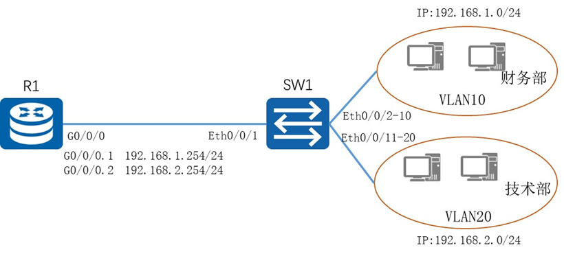
图1 网络拓扑图
2.项目规划设计
财务部和技术部分别属于VLAN10和VLAN20,使用192.168.1.0/24和192.168.2.0/24网段。二层交换机的VLAN之间是无法通信,可以通过增加一台路由器并配置相应VLAN子接口的方式,实现VLAN间的通信。现需在R1创建子接口并绑定到相应的VLAN,VLAN内部的计算机配置网关指向子接口的IP地址即可。同时,R1和SW1之间的通道需要传输多个VLAN的数据,故需配置为Trunk模式。
具体配置步骤如下:
- 配置交换机接口
- 路由器配置
- 配置各计算机的IP地址
具体规划如下表:
表1 IP地址规划表
设备 |
接口 |
IP地址 |
R1 |
G0/0/0.1 |
192.168.1.254 |
R1 |
G0/0/0.2 |
192.168.2.254 |
财务部PC1 |
192.168.1.1 |
|
技术部PC1 |
192.168.2.1 |
表2 接口规划表
本端设备 |
接口 |
端口IP地址 |
对端设备 |
R1 |
G0/0/0 |
SW1 |
|
SW1 |
E0/0/1 |
R1 |
|
SW1 |
E0/0/2 |
财务部PC1 |
|
SW1 |
E0/0/3 |
技术部PC1 |
3.项目实施
(1)配置略
(2)配置各计算机的IP地址
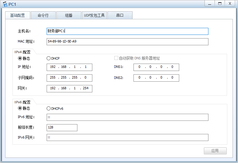
图2 财务部-PC1 IP配置图
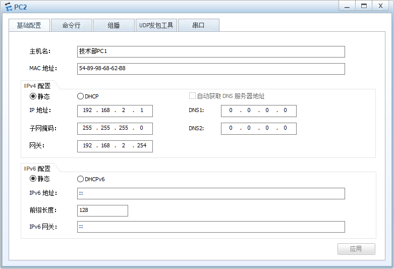
图3 技术部-PC1 IP配置图
4.项目验证
(1)验证路由器上路由表的配置信息
R1使用display ip interface brief命令查看子接口IP信息
|
[R1]display ip interface brief *down: administratively down ^down: standby (l): loopback (s): spoofing The number of interface that is UP in Physical is 4 The number of interface that is DOWN in Physical is 2 The number of interface that is UP in Protocol is 3 The number of interface that is DOWN in Protocol is 3 Interface IP Address/Mask Physical Protocol GigabitEthernet0/0/0 unassigned up down GigabitEthernet0/0/0.1 192.168.1.254/24 up up GigabitEthernet0/0/0.2 192.168.2.254/24 up up GigabitEthernet0/0/1 unassigned down down GigabitEthernet0/0/2 unassigned down down NULL0 unassigned up up(s) |
R1使用display ip routing-table命令查看路由表的配置
|
[R1]display ip routing-table Route Flags: R - relay, D - download to fib ------------------------------------------------------------------------------ Routing Tables: Public Destinations : 10 Routes : 10 Destination/Mask Proto Pre Cost Flags NextHop Interface 127.0.0.0/8 Direct 0 0 D 127.0.0.1 InLoopBack0 127.0.0.1/32 Direct 0 0 D 127.0.0.1 InLoopBack0 127.255.255.255/32 Direct 0 0 D 127.0.0.1 InLoopBack0 192.168.1.0/24 Direct 0 0 D 192.168.1.254 GigabitEthernet0/0/0.1 192.168.1.254/32 Direct 0 0 D 127.0.0.1 GigabitEthernet0/0/0.1 192.168.1.255/32 Direct 0 0 D 127.0.0.1 GigabitEthernet0/0/0.1 192.168.2.0/24 Direct 0 0 D 192.168.2.254 GigabitEthernet0/0/0.2 192.168.2.254/32 Direct 0 0 D 127.0.0.1 GigabitEthernet0/0/0.2 192.168.2.255/32 Direct 0 0 D 127.0.0.1 GigabitEthernet0/0/0.2 255.255.255.255/32 Direct 0 0 D 127.0.0.1 InLoopBack0 |
(3)测试各部门计算机的互通性
通过Ping命令,测试各部门内部通信息的情况。
使用财务部计算机PC1 Ping技术部的计算机PC2:
|
PC>ping 192.168.2.1 Ping 192.168.2.1: 32 data bytes, Press Ctrl_C to break From 192.168.2.1: bytes=32 seq=1 ttl=127 time=78 ms From 192.168.2.1: bytes=32 seq=2 ttl=127 time=78 ms From 192.168.2.1: bytes=32 seq=3 ttl=127 time=78 ms From 192.168.2.1: bytes=32 seq=4 ttl=127 time=79 ms From 192.168.2.1: bytes=32 seq=5 ttl=127 time=78 ms --- 192.168.2.1 ping statistics --- 5 packet(s) transmitted 5 packet(s) received 0.00% packet loss round-trip min/avg/max = 78/78/79 ms |