基于VLANIF的公司网络搭建
1.项目背景
Jan16公司现有财务部和技术部,使用一台24口三层交换机进行互联。为方便管理,要求为部门创建相应的VLAN,并实现VLAN间通信。项目拓扑如图1所示。具体要求如下:
- 交换机SW1为财务部创建了VLAN10,为技术部创建了VLAN20;
- 财务部的4台计算机连接在G0/0/1-4端口,技术部的9台计算机连接在G0/0/5-12及G0/0/20端口;
- 启用交换机的三层路由功能,实现部门间的相互通信;
- 拓扑测试计算机和交换机的接口信息如拓扑所示。
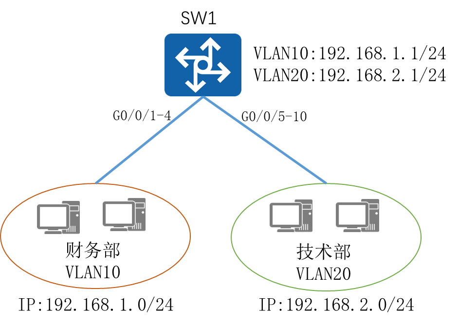
图1 网络拓扑图
2.项目规划设计
三层交换机可以通过创建VLANIF的方式实现VLAN间的通信。在交换机中创建VLAN10、VLAN20分别用于财务部、技术部的计算机接入,VLAN10使用192.168.1.0/24网段,VLAN20使用192.168.2.0/24网段。在交换机中创建VLAN10、VLAN20的VLANIF接口,并配置对应的IP地址作为计算机的网关,即可实现VLAN间的通信。
配置步骤如下:
- 在三层交换机创建VLAN,
- 将端口划分至相应VLAN
- 配置VLANIF的接口IP
- 配置各部门计算机的IP地址
项目规划如下:
表1 VLAN规划表
VLAN ID |
IP地址段 |
用途 |
VLAN10 |
192.168.1.0/24 |
财务部 |
VLAN20 |
192.168.2.0/24 |
技术部 |
表2 端口规划表
本端设备 |
端口号 |
端口类型 |
所属VLAN |
对端设备 |
SW1 |
G0/0/1 |
access |
Vlan10 |
财务部PC |
SW1 |
G0/0/5 |
access |
Vlan20 |
技术部PC |
表3 IP地址规划表
计算机 |
接口 |
IP地址 |
SW1 |
VLANIF10 |
192.168.1.1/24 |
SW1 |
VLANIF20 |
192.168.2.1/24 |
财务部-PC1 |
192.168.1.10/24 |
|
技术部-PC1 |
192.168.2.10/24 |
3.项目实施
(1)配置略
(2)配置各部门计算机的IP地址
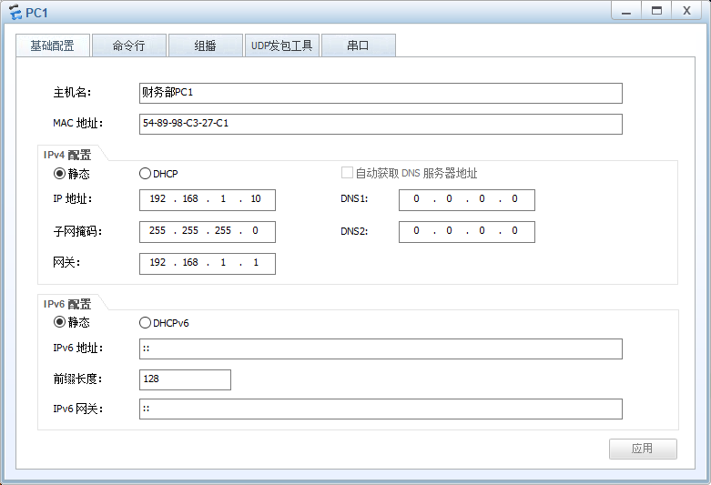
图2 财务部-PC1 IP配置图
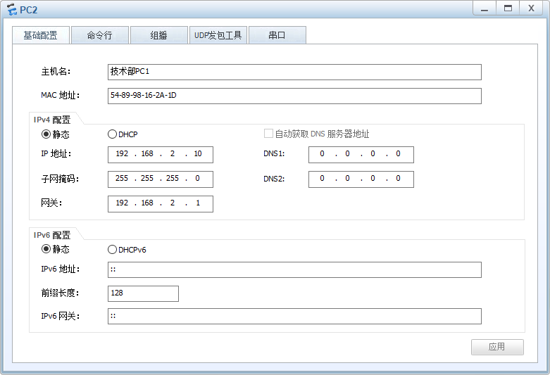
图3 技术部-PC1 IP配置图
4.项目验证
(1)验证交换机的VLAN配置信息
在SW1上使用display vlan 命令查看vlan配置信息
|
The total number of vlans is : 3 -------------------------------------------------------------------------------- U: Up; D: Down; TG: Tagged; UT: Untagged; MP: Vlan-mapping; ST: Vlan-stacking; #: ProtocolTransparent-vlan; *: Management-vlan; -------------------------------------------------------------------------------- VID Type Ports -------------------------------------------------------------------------------- 1 common UT:GE0/0/2(D) GE0/0/3(D) GE0/0/4(D) GE0/0/6(D) GE0/0/7(D) GE0/0/8(D) GE0/0/9(D) GE0/0/10(D) GE0/0/11(D) GE0/0/12(D) GE0/0/13(D) GE0/0/14(D) GE0/0/15(D) GE0/0/16(D) GE0/0/17(D) GE0/0/18(D) GE0/0/19(D) GE0/0/20(D) GE0/0/21(D) GE0/0/22(D) GE0/0/23(D) GE0/0/24(D) 10 common UT:GE0/0/1(U) 20 common UT:GE0/0/5(U) VID Status Property MAC-LRN Statistics Description -------------------------------------------------------------------------------- 1 enable default enable disable VLAN 0001 10 enable default enable disable VLAN 0010 20 enable default enable disable VLAN 0020 |
在SW1上使用display ip interface brief命令查看IP配置信息
|
[SW1]display ip int brief *down: administratively down ^down: standby (l): loopback (s): spoofing The number of interface that is UP in Physical is 3 The number of interface that is DOWN in Physical is 2 The number of interface that is UP in Protocol is 3 The number of interface that is DOWN in Protocol is 2 Interface IP Address/Mask Physical Protocol MEth0/0/1 unassigned down down NULL0 unassigned up up(s) Vlanif1 unassigned down down Vlanif10 192.168.1.1/24 up up Vlanif20 192.168.2.1/24 up up |
(2)测试各部门计算机的互通性
通过Ping命令,测试跨部门通信的情况。
使用财务部计算机PC1 Ping技术部的计算机PC2:
|
PC>ping 192.168.2.10 Ping 192.168.2.10: 32 data bytes, Press Ctrl_C to break From 192.168.2.10: bytes=32 seq=1 ttl=127 time=47 ms From 192.168.2.10: bytes=32 seq=2 ttl=127 time=32 ms From 192.168.2.10: bytes=32 seq=3 ttl=127 time=31 ms From 192.168.2.10: bytes=32 seq=4 ttl=127 time=47 ms From 192.168.2.10: bytes=32 seq=5 ttl=127 time=46 ms --- 192.168.2.10 ping statistics --- 5 packet(s) transmitted 5 packet(s) received 0.00% packet loss round-trip min/avg/max = 31/40/47 ms |
使用技术部的计算机PC2 Ping财务部的计算机PC1:
|
PC>ping 192.168.1.10 Ping 192.168.1.10: 32 data bytes, Press Ctrl_C to break From 192.168.1.10: bytes=32 seq=1 ttl=127 time=47 ms From 192.168.1.10: bytes=32 seq=2 ttl=127 time=46 ms From 192.168.1.10: bytes=32 seq=3 ttl=127 time=47 ms From 192.168.1.10: bytes=32 seq=4 ttl=127 time=63 ms From 192.168.1.10: bytes=32 seq=5 ttl=127 time=62 ms --- 192.168.1.10 ping statistics --- 5 packet(s) transmitted 5 packet(s) received 0.00% packet loss round-trip min/avg/max = 46/53/63 ms |